
A correctly positioned hole can still fail an edge inspection. The coordinates match the drawing, yet the glass around the opening is damaged. For a processing team, the next question is what happened where the tool met the glass. Spindle runout offers one explanation, and understanding it helps separate a location problem from a rotating-tool problem.
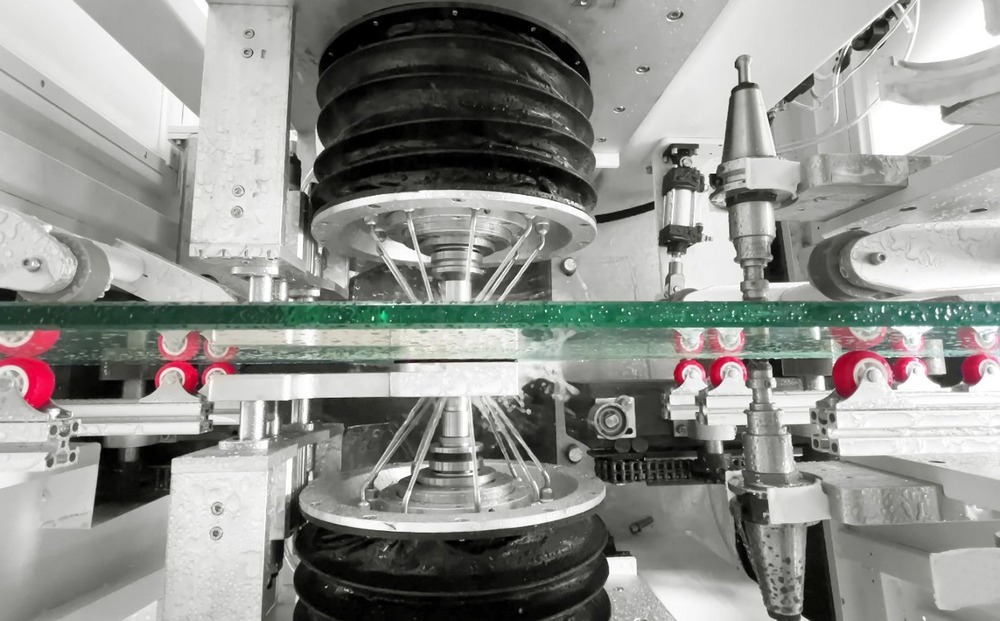
How Uneven Rotation Reaches the Hole Edge
Radial runout describes a tool’s sideways variation as it rotates around its intended axis. Its working surface then sweeps an uneven envelope. The spindle, holder and tool contribute to that assembled condition. Quoting the spindle specification alone leaves out what happens at the holder interface and along the installed tool.
A diamond core drill removes a circular groove around a central core. If the assembly rotates off-center, its contact with the glass becomes uneven. Clearance between the drill tube and the hole also matters because tube contact can damage the edge. These relationships make concentricity relevant to both hole geometry and finish.
The hole center tells only part of the story on a máquina de perfuração de vidro. It cannot tell you whether the tool followed a concentric path. When a defect keeps appearing with one tool, compare its hole diameter and edge condition with the programmed position before changing the drawing.
Position Accuracy and Concentricity Are Different
Position accuracy concerns where the machine places a feature. Concentricity concerns how the tool rotates around its axis. A correct center coordinate can coexist with an oversized or damaged opening, so changing coordinates is an unsuitable response to a problem originating in the rotating assembly.
Maximum Speed Does Not Describe Edge Quality
Maximum rpm tells you little about the edge on a particular job. The diamond tool, feed and coolant delivery all contribute to the result. A speed rating is useful equipment information, but it cannot replace a comparison using the glass and tooling that will actually run through production.
Why the Holder Matters Alongside the Spindle
The holder is where spindle accuracy meets the installed tool. Wear, contamination or poor seating there can introduce error even when the spindle itself is capable. Before attributing a chipped edge to spindle damage, separate the condition of the spindle from that of the holder and complete tool assembly.
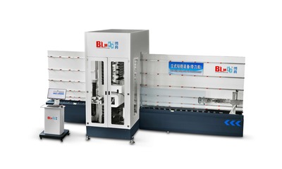
An automatic changer makes the tool interface particularly relevant to repeatability. BLM Automatic Machine’s A71X máquina de perfuração vertical de vidro uses BT40 holders and automatic tool change. For an equipped drilling-and-milling configuration, the relevant question is how each installed assembly seats and performs across its assigned operations.
Consistent seating matters whenever the machine returns to an assembly. If the same tool produces a different result after being changed, include the seating interface in the investigation. Compare the assembled condition before and after the change rather than assuming that the stored tool identity guarantees identical rotational behavior.
What Drilling and Milling Reveal About the Assembly
Drilling and milling expose the glass to different tool paths. Drilling creates holes, while milling follows contours for features such as shaped openings. On an A71X configured for both, inspect the drilled edge and the milled feature independently. A satisfactory result from one operation does not validate the other automatically.
Tool identity gives a finish complaint something concrete to follow. On a máquina de molhamento de vidro, record which assembly produced the feature being inspected. “Poor finish” could describe several different observations in CNC glass machining. A note identifying the tool, operation and damaged area is a better basis for comparison.
|
Observation |
What it helps distinguish |
Next comparison |
|---|---|---|
|
Defect follows one tool |
Tool or holder contribution |
Another approved assembly |
|
Hole position is correct, edge is poor |
Location versus local machining quality |
Diameter and edge condition |
|
Drilled hole passes, milled contour fails |
Operation-specific behavior |
Milling tool and process |
|
Finish changes after a tool change |
Seating or assembly change |
Before-and-after records |
Comparisons are only useful when the other conditions are understood. Keep the glass type, thickness and approved machining conditions consistent where possible; a changed feed or material can obscure the difference. Treat the patterns above as leads to investigate, not proof that a bearing or spindle has failed.
Evidence That Separates Runout from Other Causes
Measurement on a CNC machine for glass is more useful when its location is explicit. A runout value taken near the holder and one taken farther along the tool describe different measurement conditions. Ask the responsible technician to identify the measurement point, assembled tooling and applicable limit before comparing readings or judging an assembly acceptable.
Hole inspection should remain equally specific. Record the face where damage appears and whether it affects the entire circumference or a localized area. Excessive coolant pressure can eject the core prematurely and worsen breakout; inappropriate feed can also increase chipping. Edge damage alone therefore cannot identify runout as its cause.
The most useful production record connects the observation to the actual tool:
Identify the holder position, tool and machining operation.
Separate hole location, diameter and edge observations.
Compare the same glass and approved process conditions.
Physical measurement and tool handling belong to qualified personnel following the machine’s approved procedure. Do not inspect a rotating assembly by touch or alter operating parameters simply to conceal a defect. The objective is to establish a repeatable cause, then verify the correction on representative work.
A Clearer Way to Judge Hole Quality
The complete rotating assembly is the right unit of investigation. Keep hole location separate from concentricity, include the holder and tool, and assess drilling and milling on their own results. With those distinctions clear, a production team can investigate an edge defect without prematurely committing to a spindle replacement.
If you need help relating an A71X hole-edge issue to its installed tooling and drilling or milling configuration, please contact us.
FAQ
Can runout affect a correctly positioned hole?
Yes. The programmed center and the tool’s rotational path describe different aspects of accuracy. A hole can be located correctly while its diameter or edge condition remains unacceptable because of the assembled tooling or process conditions.
Does every chipped edge indicate spindle damage?
No. Tool condition, holder seating, feed and coolant behavior can also affect the result. Treat chipping as an observation to investigate, with runout as one possible contributor rather than an automatic diagnosis.
Does BT40 guarantee a particular runout tolerance?
No. BT40 identifies the holder interface used on A71X. The applicable tolerance must relate to the installed assembly and measurement conditions; the interface designation alone does not establish finished-hole accuracy.
Why inspect milling after drilling passes?
The operations use different tool paths and may use different tools. A good drilled hole does not establish that the milling assembly produces an acceptable contour on the same panel.
Can two runout readings be compared directly?
Only when their measurement conditions are comparable. Record where each reading was taken and which holder and tool were assembled. Apply the appropriate acceptance limit rather than comparing unidentified numbers from different setups.