
A hole pattern can be correct on the drawing and still fail on the first glass sheet when its coordinates are typed into production twice. In CNC drilling and milling for glass, drawing data often passes from design to planning and then to an operator. Every re-entry creates a chance to swap a coordinate, omit a feature, or load the wrong revision. CAD/DXF import reduces those handoffs, but only when the file, program, and first-off check remain connected.
Where Drawing Errors Enter the Process
Drawing errors usually enter at the point where geometry becomes machine instructions. In precision glass drilling, a designer may work from a current CAD file, while production receives a printed list, a copied coordinate table, or a separately rebuilt program. The result can look plausible because the machine follows its instructions perfectly, even though the instructions no longer match the released drawing.
Coordinate transcription hides small mistakes
Manual entry is most vulnerable when a part has repeated holes, mirrored features, or several diameters. One digit, decimal point, or axis direction can change a pattern without making the program obviously invalid. A document can also lose context: units, orientation, and the drawing revision may sit outside the coordinate list that reaches the machine.
A correct file can still become a wrong job
File transfer solves only one part of the problem. Similar filenames, unapproved revisions, and unmarked glass orientation can still send the wrong job to the table. The useful goal is a controlled chain from released drawing to imported geometry, approved first piece, and repeatable batch program.
What CAD/DXF Import Actually Protects
CAD/DXF import protects the geometric information that is easiest to distort during repeated handling. The intended hole centers, spacing, contours, and feature relationships arrive as a drawing rather than as a freshly typed interpretation. It does not replace process judgment, yet it removes a needless translation step before the operator checks the setup.
|
Handoff point |
What must stay unchanged |
Error prevented |
|
Drawing release |
Revision, scale, units, and feature coordinates |
A previous or mismatched drawing entering production |
|
Import review |
CAD/DXF geometry and programmed hole data |
Manual coordinate transcription or skipped features |
|
First-off check |
Hole centers, diameters, and pattern orientation |
A correct file paired with an incorrect setup |
|
Batch release |
Approved program and barcode or job reference |
Operators selecting a similar but wrong program |
A98 Workflow: From Drawing to Drilling
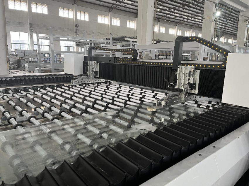
For a shop that handles mixed orders, the practical value of a стеклянная буровая и фрезерная машина is its ability to keep the drawing and the operation close together. The A98 uses an industrial computer for online drawing and can work with barcode scanning and ERP connections. Existing CAD, DXF, and hole-format drawings can be copied to the equipment computer for drilling.
Import needs a deliberate release point
The operator should import only a released drawing with a visible revision identifier. Before glass reaches the table, compare overall size, hole count, critical dimensions, units, and processing face with the job order. This review catches mistakes that file import cannot detect, such as a correct drawing selected for the wrong customer order.
The machine must receive usable geometry
For glass milling, a clean import starts with a file that separates intended processing geometry from clutter. Remove obsolete construction layers, confirm that holes are closed and correctly sized, and use a shared convention for units and origin. These habits make CAD/DXF import faster to review and reduce the temptation to repair geometry at the machine during production.
The First-Off Check Still Has a Job
The first-off check confirms the manufacturing result, not just the import. For precision glass drilling, measure the hole centers and diameters that matter most, then inspect the pattern orientation on the actual sheet. If glass milling follows in the same job, check the relationship between the holes and the milled features before releasing the batch.
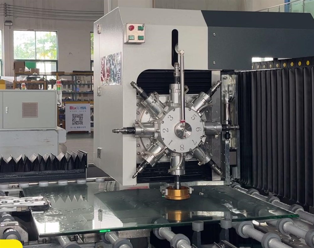
This matters particularly in glass CNC machining, where one part can contain different hole diameters and a milled opening. At BLM Automatic Machine, our A98 uses a rotating tool magazine and optional milling function, allowing drilling, milling, and polishing work to stay on one integrated machine. That makes the approved drawing-to-part relationship easier to review as one job.
- Use one revision-controlled filename and retain the job number in the program record.
- Confirm drawing units, material size, processing face, and glass orientation before import approval.
- Measure a representative first piece before the operator releases a repeated pattern.
- Keep the approved program linked to the barcode or work order used for the batch.
When Imported Geometry Needs Investigation
An imported drawing should be paused when the visual preview differs from the released document, when dimensions look scaled, or when the pattern sits in an unexpected location. Do not correct a doubtful job by shifting individual coordinates until the file origin, units, and revision are understood. That approach can hide the real break in the workflow.
Glass milling adds another reason to confirm the job before cutting. Tool diameter, contour direction, glass support, and water conditions affect the finished edge, even when the imported path is correct. Keep those process settings in the approved program record so a later batch does not inherit drawing data without its necessary manufacturing context.
Practical Takeaway
CAD/DXF import is most useful when it removes re-entry without removing accountability. Preserve the released geometry, review the imported job before cutting, verify a first piece, and lock the approved program to the batch reference. With that chain in place, the team can spend less time rebuilding hole patterns and more time confirming that the glass matches the intended design.
Часто задаваемые вопросы
Can CAD/DXF import eliminate all glass drilling errors?
No. It reduces errors created by manual coordinate transcription, but it cannot verify that the selected file, units, glass orientation, material, tooling, or setup are correct. A measured first piece remains the practical confirmation that the full process matches the drawing.
What should be checked before importing a DXF file?
Check the drawing revision, units, overall glass size, intended processing face, hole count, and critical feature dimensions. Review the visual preview before machining. These checks are quick and help reveal a scale, orientation, or version mismatch before glass is processed.
Does the A98 accept CAD and DXF drawings?
The A98 industrial computer can receive existing CAD, DXF, and hole-format drawings copied to the equipment computer for drilling. It also supports online drawing and can work with barcode scanning and ERP connections, subject to the planned production configuration.